
Conventionally power transmission is affected through High Voltage AC systems all over the world.HVAC transmission is having severe limitations like line length, uncontrolled power flow, over/low voltages during lightly / overloaded conditions, stability problems, fault isolation, etc. Considering the disadvantages of the HVAC system and the advantages of HVDC transmission, the power grid has chosen HVDC transmission for transferring 2000MW from ER to SR.
| Converter Transformers | AC System Parameters |
| DC- Yard | AC Bus Bar |
| Operation Modes and DC Switchyard Configurations | AC Protection |
| Basic Power System Control | Filter Circuits |
| DC Protection | AC Filters |
| Communication Equipment | PLC Noise Filters |
| Converters | DC Filters |
| Smoothing Reactor | AC System Parameters |
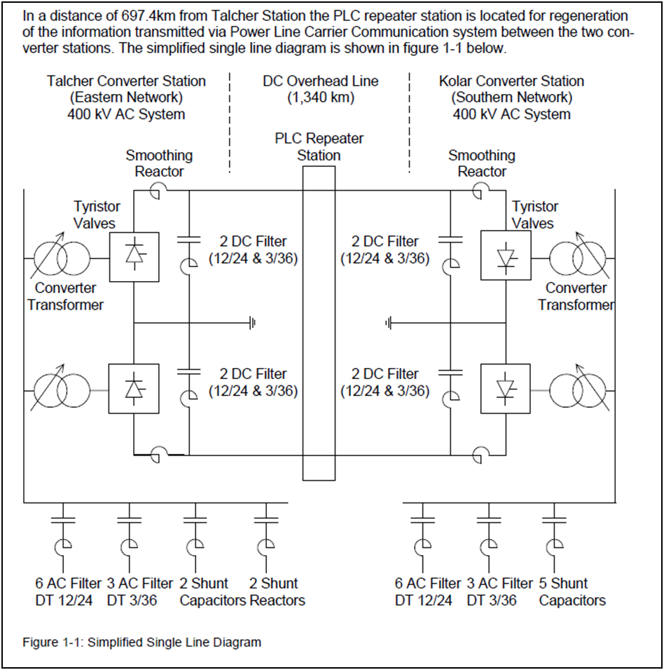
The special feature of the HVDC system is the DC circuit consisting of one 12- pulse 3- phase converter in each valve hall. The converters of the valve halls are interconnected on the high voltage side via smoothing reactors and DC overhead lines to the corresponding converters of the valve halls.
Step up of the valve voltage to the line AC voltage is carried out by three single-phase converter transformers for each 12- pulse converter (in total 6 transformers plus one spare transformer per station).
In Talcher, three filter banks with shunt capacitors, double tuned ac filters, and shunt reactors, 4 very short ac lines to the NTPC yard are connected to a common ac bus together with the converters including converter transformers.
In Talcher at NTPC yard, there are 6 generators (each 500MW), 6 ac transmission lines, 2 autotransformers,2 startup transformers, and 4 very short ac lines to the HVDC ac yard connected to one common ac bus.
The interconnection between the NTPC ac yard and the Powergrid ac yard for the HVDC is done via 4 very short ac overhead lines.
In Kolar station, three filter banks with shunt capacitors and double-tuned ac filters, two auto-transformers (one of this is a future extension), 8 ac lines (one of this is a future extension) are connected to a common ac bus together with the converters including converter transformers. Automatic control is carried out by digital controllers. Digital relays take care of protection.