

Purpose
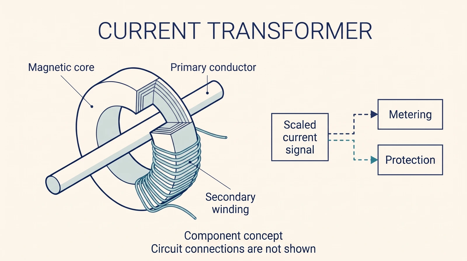
A current transformer, or CT, provides a reduced representation of current to instruments and protective relays. Metering and protection applications can have different requirements, so a CT must be selected for its intended use.
Construction and ratio
The primary can be a conductor passing through a core or a winding, depending on the design. The ratio relates the primary current to the secondary current under specified conditions; the equipment rating and connected burden affect its use.
Documentation and testing
Ratio, polarity, insulation and burden are among the topics addressed in the cited training text. They are not interchangeable checks. CT secondary circuits require equipment-specific safety procedures; do not alter a live circuit based on this overview.
Understanding ratio
A CT marked 300:5 has a nominal primary-to-secondary ratio of 60:1. In an ideal illustration, 150 A primary corresponds to 2.5 A secondary. Actual accuracy depends on the device, burden and operating conditions; the ratio alone does not describe the complete error performance.
Burden and polarity
Burden is the load presented to the CT secondary by connected instruments, relays and wiring. It is commonly expressed in volt-amperes at a stated secondary current. Polarity markings establish the relative directions of primary and secondary quantities; correct polarity matters when a relay compares currents from several locations.
A serious secondary-circuit hazard
Do not open the secondary of an energized CT. The cited training text warns that an open secondary can develop a dangerous voltage and overheat the core. Work involving CT circuits must follow the specific installation’s approved safety and isolation procedures.
Metering versus protection
A metering CT is selected to represent operating current accurately for instruments, while protection CTs must suit the relay and fault conditions. Saturation and excessive burden can distort what a relay sees. The CT and the complete secondary circuit therefore need to be considered together.
Choosing the right evidence
The nameplate establishes nominal ratio and device identification, while the manufacturer’s documentation specifies the conditions for its accuracy and application. A protection study also considers connected leads and relay inputs. Do not identify a CT’s protective performance solely from a photograph or the numerical ratio.
Further reading
Bharat Skills Electrician (Power Distribution), revised 2022, pp. 163–166.