Basic principle
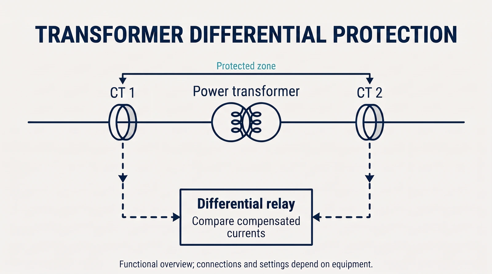
Differential protection compares currents associated with the boundaries of a protected zone. A difference can indicate a fault within the protected equipment, but measurement and transformer behavior must be considered in the protection design.
Why compensation matters
Current transformer ratios and transformer winding connections affect the relationship between measured currents. The Siemens manual describes matching and compensation as part of its transformer differential protection function.
Distinguishing abnormal conditions
Transformer energization and current-transformer behavior can influence measured current. Protection algorithms account for such conditions according to the relay and application. Settings and commissioning require the actual transformer data, relay manual and protection study.
Inside and outside the zone
Imagine currents measured at the boundaries of a two-ended protected zone. After the measured currents are referred to a common base and compensated for transformer phase displacement, their signed sum is approximately zero for ideal healthy through-flow. A fault inside the zone can draw current into the fault from one or both sides, producing a differential quantity. Actual measurements are not ideal.
Making the currents comparable
Transformer primary and secondary currents differ in magnitude, and winding connections can introduce phase displacement. The Siemens manual describes mathematical magnitude and vector-group matching before comparison. Correct CT ratios, polarity and transformer data are necessary for the comparison to make sense.
External faults and restraint
A fault outside the zone may produce a large through-current. Current transformers can respond differently, particularly if one saturates, creating an apparent differential current. A restraint characteristic is used to reduce unwanted operation in this situation while retaining sensitivity to faults inside the zone.
Tap changing and current comparison
Changing transformer taps changes the effective transformation ratio over the regulating range. The Siemens manual explains that this can contribute to differential current even when the transformer is not internally faulted. The relay’s matching and restraint design must account for the actual transformer and regulating range.
Inrush is not automatically an internal fault
When a transformer is energized, magnetizing inrush can create a large current that does not represent an internal short circuit. The cited relay offers methods including harmonic-based restraint. The particular relay design and protection study determine how that feature is applied; a general explanation cannot determine settings.