
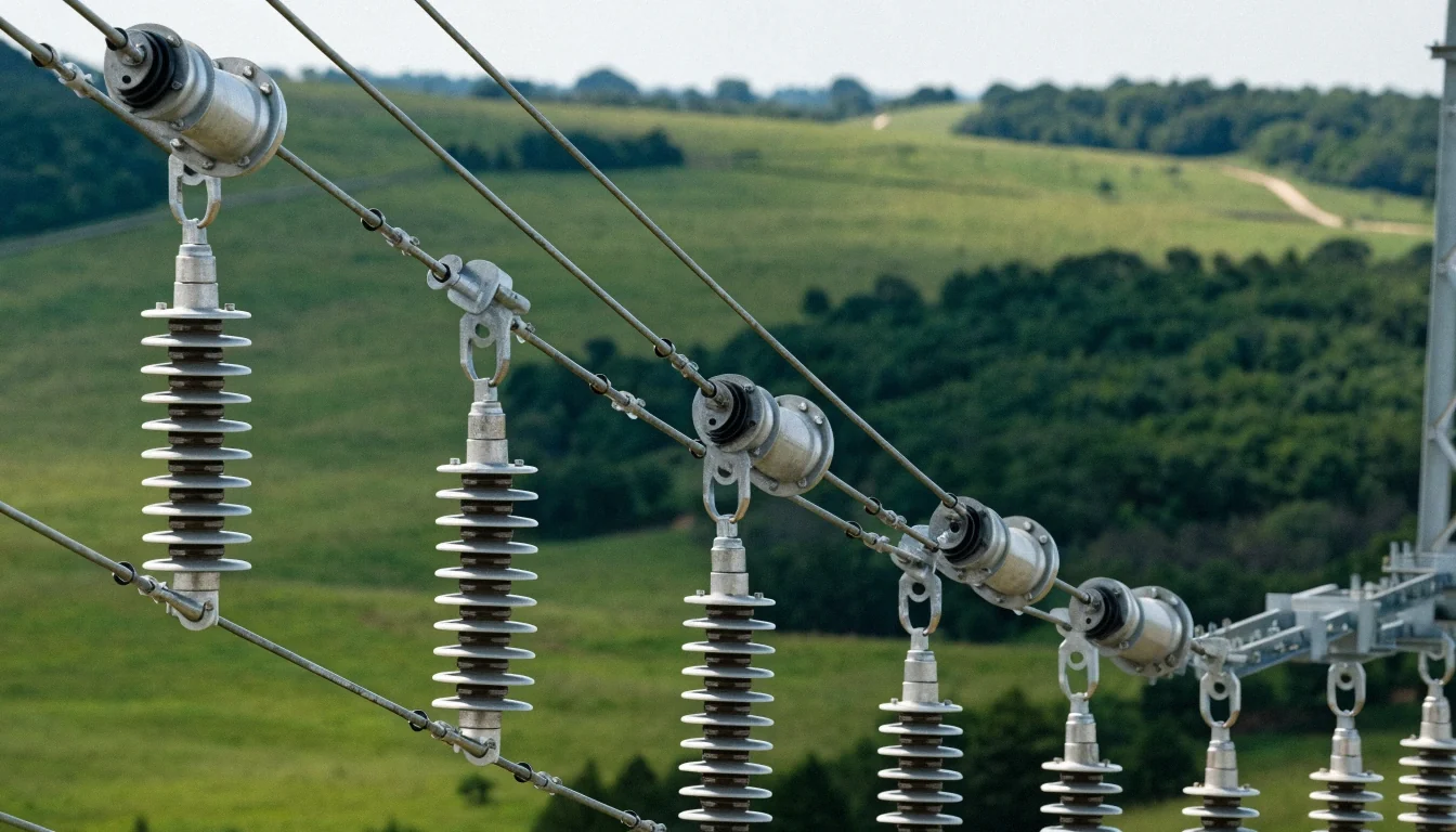
This electrical transmission line training course introduces basic safe operational and field diagnostics of transmission towers and lines with a focus on safe operation, testing, and maintenance of normally installed EHT systems.
Definition
The transmission line is made up of a conductor having a uniform cross-section along the line.
The electrical tower is made up of steel and is used for supporting the conductor of the transmission line and Air acts as an insulating/dielectric medium in between.
Transfer of Bulk power from the generating station or Substation to the load centers.
Power transmission at higher voltage and reduced current for the same quantum of energy thereby reducing the line loss.
Efficient, Safe, and reliable power supply.
Classification of Transmission Lines
As per Line Length
ØShort Transmission Line(Upto 50Km)
ØMedium Transmission Line(50-150Km)
ØLong Transmission Line(Above 150Km)
As per Voltage Level
Ø0- 250(LV/LT)
Ø251-650(MV/MT)
Ø651-33KV(HV/HT)
Ø33KV-765KV(EHV/EHT)
Ø765KV Above(UHV/UHT)
Components of Transmission Line
ØTransmission Tower
ØConductor
ØHardware Fittings
ØEarth wire/OPGW
ØInsulator
ØJumper
ØVibration Damper
ØSpacers
ØArcing Horn
Different Types of Transmission Tower
Type A Tower (Tangent Tower with Suspension String)
—-Used on straight runs and up to 2 Degree Deviation
Type B Tower (Small Angle Tower with Tension String)
—–Used for line deviation from 2 Degree to 15 Degree Deviation
Type C Tower (Medium Angle Tower with Tension String)
——Used for line deviation from 15 Degree to 30 Degree Deviation
ØType D Tower (Large Angle Tower with Tension String)
—-Used for line deviation from 30 degrees to 60 Degree Deviation
ØType E Tower (Dead End Tower with Tension String)
—Used For line termination & Starting
ØSpecial Type Tower
—- (Span=1000m)
Used for River Crossing & Mountain Crossing
ØTransposition Tower Used for Transposition of line
Transmission line Corridor Clearance
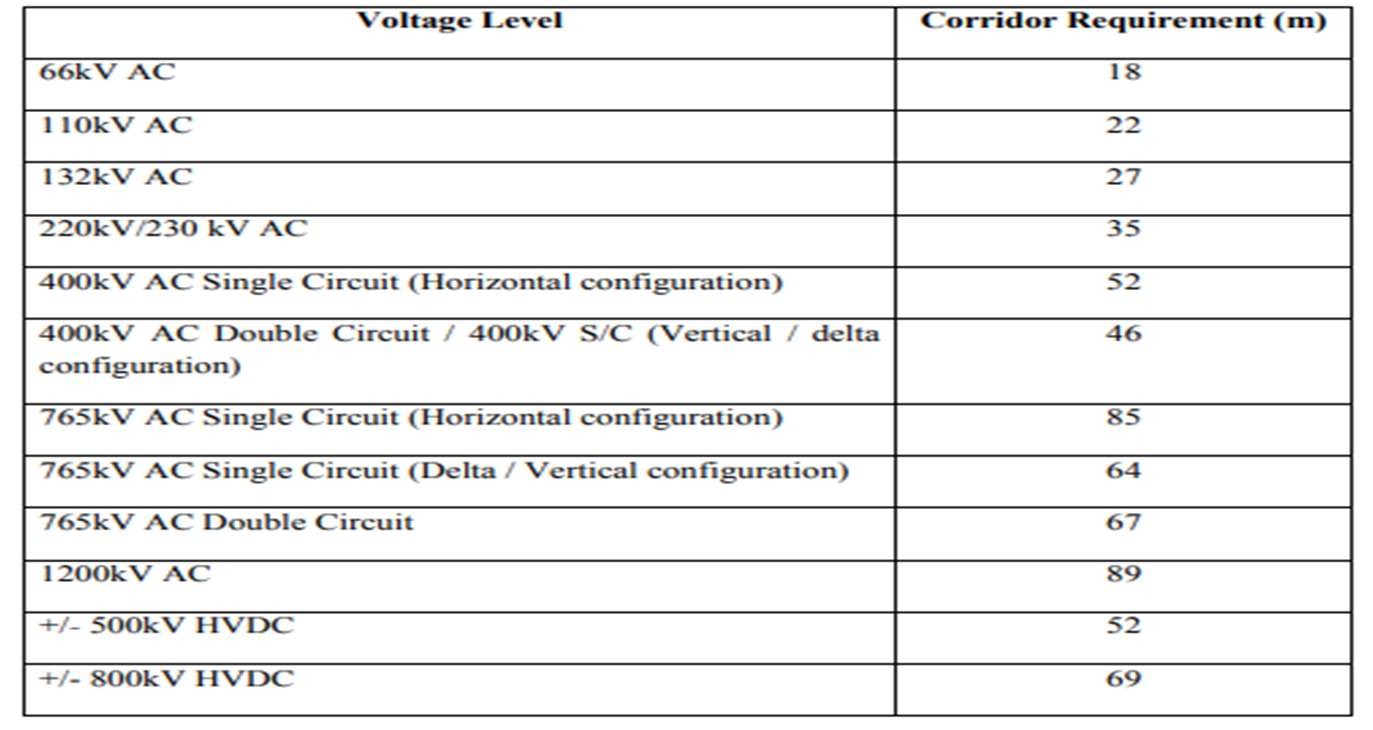
Values transcribed from the accompanying figure. Its jurisdiction, conditions and current applicability are not established; do not use these figures as design clearances.
| Voltage Level | Corridor Requirement (m) |
|---|---|
| 66 kV AC | 18 |
| 110 kV AC | 22 |
| 132 kV AC | 27 |
| 220/230 kV AC | 35 |
| 400 kV AC single circuit, horizontal | 52 |
| 400 kV AC double circuit / single circuit, vertical or delta | 46 |
| 765 kV AC single circuit, horizontal | 85 |
| 765 kV AC single circuit, delta or vertical | 64 |
| 765 kV AC double circuit | 67 |
| 1200 kV AC | 89 |
| ±500 kV HVDC | 52 |
| ±800 kV HVDC | 69 |
Transmission line Clearance
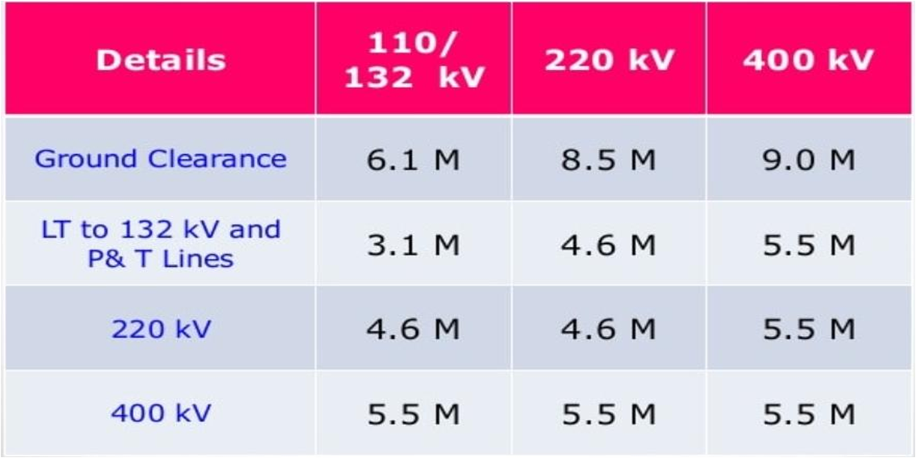
Values transcribed from the accompanying figure. Its jurisdiction, conditions and current applicability are not established; do not use these figures as design clearances.
| Details | 110/132 kV | 220 kV | 400 kV |
|---|---|---|---|
| Ground Clearance | 6.1 | 8.5 | 9.0 |
| LT to 132 kV and P & T Lines | 3.1 | 4.6 | 5.5 |
| 220 kV | 4.6 | 4.6 | 5.5 |
| 400 kV | 5.5 | 5.5 | 5.5 |