
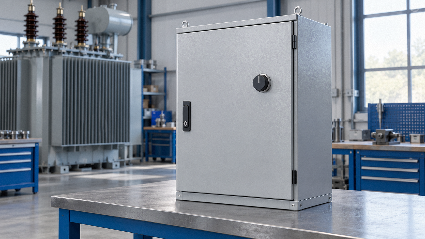
An on-load tap changer (OLTC) lets a transformer adjust its voltage ratio in steps while continuing to supply its load. It changes which winding tap is in use, helping the system respond to variations in operating conditions.
Why change taps?
A transformer with a fixed ratio cannot adjust that ratio when demand and voltage conditions vary. An OLTC selects among winding taps to change the ratio in steps. The NIMI electrician training text describes changing load and the resulting voltage variation as one reason for regulation. An automatic voltage regulator may request a higher or lower tap position; the text also describes manual control. The exact control arrangement depends on the installation.
How one resistive design changes position
A tap change must maintain the supply while preventing a direct short across the winding section between adjacent taps. In the resistive design described by NIMI, tap selection and the switching of load current are handled by separate components. During transfer, a temporary resistive path connects the adjacent taps. Once the transfer is complete, current flows through the normal path for the selected tap.
This is a description of one resistive switching principle, not a universal contact sequence. The same training text identifies both resistive and reactance types of load tap changer. Construction, switching arrangements and controls vary; the equipment manufacturer's documentation governs the particular device. See NIMI, Electrician (Power Distribution), 2nd Year Theory, PDF pages 138–139.
Regulation and protection
An OLTC is regulating equipment, not a substitute for protection. Siemens describes tap changers as part of normal voltage regulation and notes that a tap changer malfunction in the high-voltage direction can contribute to overvoltage. Excessive voltage can damage insulation. The same manual describes overvoltage protection functions that can provide alarms or trips according to the scheme's design.
Tap position also matters to transformer differential protection. In its 7SR242 manual, Siemens identifies the effects of an OLTC as one source of steady-state error considered by the relay's first bias slope. This is an example from a particular protection device, not a recommended setting. See Siemens 7SR242 Duobias technical manual, PDF pages 34 and 328.
Safety and scope
“On-load” describes the equipment's intended switching function; it does not mean that energized equipment is safe to inspect, open, adjust or repair. Never work on energized equipment using this overview as an instruction. Inspection, operation and maintenance require qualified personnel, the applicable equipment documentation and approved safety procedures. This article does not provide operating instructions or protection settings.